26/07/22
ST1S14PHR Power Regulator: Specs, Pin Description & Applications
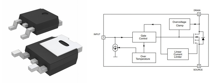
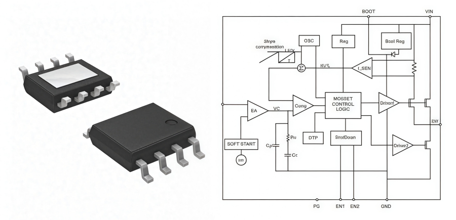
OverviewThe ST1S14PHR is a 3A step-down monolithic switching regulator designed for efficient DC/DC power conversion. It integrates a high-side N-channel DMOS transistor with a typical RDS(on) of 200mΩ, supporting a compact design with fewer external components. The output voltage is adjustable from 1.22V, with a fixed 850kHz switching frequency provided by the internal oscillator.The device is available in an HSOP8 package with exposed frame, offering improved thermal performance for high-current applications. It also integrates a Power Good output, pulse-by-pulse current limit, short-circuit protection, and current foldback protection, making it suitable for industrial equipment, embedded systems, and other power management applications.(Contact us for a quote) Basic SpecificationsParameterValuePart NumberST1S14PHRDescriptionIC REG BUCK ADJ 3A 8HSOPManufacturerSTMicroelectronicsLead Free Status / RoHS StatusLead free / RoHS CompliantSynchronous RectifierNoMoisture Sensitivity Level (MSL)1 (Unlimited)FunctionStep-DownOutput TypeAdjustableTopologyBuckNumber of Outputs1Voltage - Input (Max)48VVoltage - Output (Max)43.2VVoltage - Output (Min/Fixed)1.22VMounting TypeSurface MountVoltage - Input (Min)5.5VOutput ConfigurationPositiveOperating Temperature-40°C ~ 125°C (TJ)Current - Output3APackage / Case8-SOIC Base Part NumberST1S14 Pin Description1. BOOT: Bootstrap capacitor for N-channel gate driver. Connects 100 nF low ESR capacitor from BOOT pin to SW2. PG: Power good3. EN1: Enable pin active low4. FB: Feedback voltage5. EN2: Enable pin active high6. GND: Ground pin7. VIN: Input supply pin8. SW: Switching node Key Featuresl 3 A DC output currentl Operating input voltage from 5.5 V to 48 Vl 850 kHz internally fixed switching frequencyl Internal soft-startl Power good open collector outputl Current mode architecturel Embedded compensation networkl Zero load current operationl Internal current limitingl Inhibit for zero current consumptionl 2 mA maximum quiescent current over temperature rangel 250 mΩ typ. RDS(on)l Thermal shutdown Functional Block Diagram AnalysisThe ST1S14 is based on a “peak current mode”, constant frequency control. As a consequence, the intersection between the error amplifier output and the sensed inductor current generates the control signal to drive the power switch.The main internal blocks shown in the block diagram are:l A fully integrated sawtooth oscillator with a typical frequency of 850 kHzl A transconductance error amplifierl A high side current sense amplifier to track the inductor currentl A pulse width modulator (PWM) comparator and the circuitry necessary to drive the internal power elementl Soft-start circuitry to decrease the inrush current at power-upl Current limitation circuit based on the pulse-by-pulse current protection with frequency divider based on FB voltage and the hiccup protectionl Bootstrap circuitry to drive the embedded N-MOS switchl A multi input inhibit block for standby operationl A circuit to implement the thermal protection function(Contact us for a quote) Hardware Design & TopologyThe ST1S14PHR uses an asynchronous Buck topology, where the high-side MOSFET and external Schottky diode work together to convert high input voltage into a stable output voltage. Proper selection of external components helps improve efficiency, reduce ripple, and ensure reliable operation. 1. Input Capacitor (CIN)The input capacitor reduces switching noise and input voltage ripple.l Use low ESR/ESL X5R or X7R MLCC capacitors.l Recommended capacitance: 10μF–22μF, with a 100nF bypass capacitor placed close to VIN and GND pins.l Voltage rating should be at least 1.5–2 times the maximum input voltage to avoid DC bias effects. 2. Schottky Diode (D1)The external diode provides the current path when the MOSFET turns off.l Reverse voltage rating should meet: VRRM ≥1.25×VIN,MAXl Select low forward voltage (0.4–0.55V) Schottky diodes to reduce conduction loss and improve efficiency. 3. Power Inductor (L)The inductor stores energy and controls output ripple current.l Recommended ripple current ratio: 20–40% of output current.l Saturation current should be higher than peak inductor current with 20–30% margin.l Current rating should support the maximum continuous output current. 4. Feedback Resistors (R1/R2)The feedback network controls output voltage regulation.VOUT=1.22V×(1+R2/R1)l Use 1% precision resistors for accurate voltage control.l Recommended R2 range: 10kΩ–100kΩ. 5. Bootstrap Capacitor (CBOOT)The bootstrap capacitor provides the gate drive voltage for the high-side N-MOSFET.l Place a 100nF / 50V low-ESR X7R ceramic capacitor close to the BOOT and SW pins.l Keep the connection short to reduce switching noise and improve stability. Software Integration and Debug1. Communication Interfaces and Control ModesThe device supports SPI, I²C, and MDIO/MDC interfaces for configuration and monitoring. SPI provides high-speed register access, I²C is used for low-speed control, and MDIO supports PHY status monitoring and IEEE 802.3 register access. Proper clock settings and reset timing are required before register initialization. 2. Embedded/Linux Driver SupportFor Linux integration, the device is configured through the Device Tree, including bus address, compatible settings, PHY mode, speed, and MAC mapping. The Linux DSA framework is commonly used to manage each switch port as an independent network interface. 3. Debugging and Fault DiagnosisSystem debugging relies on status registers, MIB counters, and loopback functions. Link status, auto-negotiation errors, CRC errors, and packet loss can be monitored for troubleshooting. Fault flags such as over-temperature and UVLO help improve system reliability. Typical Application ScenariosThe ST1S14PHR is a high-current step-down switching regulator capable of delivering up to 3A output current, making it suitable for applications that require efficient power conversion, stable voltage regulation, and compact power solutions. 1. Factory Automation EquipmentST1S14PHR is suitable for industrial automation systems that require stable power supplies for controllers, sensors, and communication modules. Its high-current capability and protection functions help maintain reliable operation in continuous industrial environments. 2. Printers and Office EquipmentThe regulator can provide efficient DC power conversion for printers and multifunction devices, supporting motors, control circuits, and electronic modules that require stable voltage rails. Its compact design helps reduce the size of power management circuits. 3. DC-DC Power ModulesWith adjustable output voltage starting from 1.22V and an integrated high-side MOSFET, ST1S14PHR can be used as a core component in compact DC-DC converter modules. It simplifies circuit design while providing high conversion efficiency for various voltage regulation needs. 4. High-Current LED Driver ApplicationsThe device can support LED lighting systems that require stable current delivery and efficient voltage conversion. Its high output capability and thermal performance make it suitable for driving high-power LED loads in industrial and commercial lighting applications. 5. Embedded Systems and Control BoardsST1S14PHR provides a reliable power solution for embedded systems that integrate processors, communication chips, and peripheral devices. Its small package size and integrated protection features help improve system reliability while reducing external components.(Contact us for a quote) How Does ST1S14PHR Work as a Buck Converter?The ST1S14PHR operates as an asynchronous buck converter, using an internal high-side N-channel DMOS switching transistor together with an external freewheeling diode to convert a higher input voltage into a stable lower output voltage. When the internal switch is turned on, energy is delivered from the input source to the load through the inductor while the inductor stores energy. When the switch turns off, the inductor releases stored energy through the external diode, maintaining continuous current flow and achieving smooth voltage step-down conversion.The device integrates a fixed 850kHz oscillator and uses PWM control to adjust the switching duty cycle, ensuring stable output regulation. The feedback pin continuously monitors the output voltage and adjusts the switching operation according to the set value. In addition, the ST1S14PHR features cycle-by-cycle current limiting, short-circuit protection, and current foldback protection, helping reduce power stress under abnormal conditions and improve overall system reliability. Package Dimensions ANDE Electronics: Your Trusted Partner in Electronic Component Sourcing At ANDE Electronics, we make getting the electronic components you need simple and fast. We work directly with top global manufacturers to provide high-quality components that have passed our strict checks, so you can count on them for your projects.We also focus on quick and consistent delivery to keep your work on schedule and avoid delays. When you need reliable and efficient electronic parts for your projects, ANDE Electronics is a partner you can trust.(Contact us for a quote)
150

26/07/22
AUO G084SN03A V3: 8.4’’ IndustrialA TFT LCD Module Guide
G084SN03 V3 OverviewAUO G084SN03 V3 is an 8.4'' color TFT-LCD module for industrial displays. It supports SVGA resolution (800 × 600 pixels) and delivers high-quality image output with 16.2M colors (RGB 8-bit) or 262K colors (RGB 6-bit), meeting the display requirements of industrial equipment and embedded systems.The module adopts an LVDS interface for stable signal transmission and integrates an LED driver to simplify system design and improve backlight reliability. As a RoHS-compliant product, G084SN03 V3 provides a reliable display solution for industrial control panels, automation equipment, and other long-term operating applications.(Contact us for a quote) G084SN03 V3 Basic SpecificationsThe basic specifications of the G084SN03 V3 TFT-LCD module cover key parameters such as screen size, resolution, display mode, interface type, backlight design, and operating environment, providing important references for engineers during display solution selection and replacement design.Parameter ValueBrandAUOModelG084SN03 V3Size8.4"CompositionLCMResolution800(RGB)×600, SVGA 119PPILuminance250 cd/m² (Typ.)Contrast Ratio600 : 1 (Typ.) (TM)Viewangle80/80/80/60Color Depth262K/16.2M 45% NTSCLight Source3 strings WLED , 30K hours , With LED DriverInterface TypeLVDS (1 ch, 6/8-bit) , 20 pins ConnectorActive Area173.8(W)×131.2(H) mmPixel FormatRGB Vertical StripeFrame Rate60HzTouchscreenWithoutVoltage Supply3.3V (Typ.)WeightTBDOutline Size203(W)×142.5(H) ×6.2(D) mmMax RatingsOperating Temperature: -20 ~ 70 °C ; Storage Temperature: -20 ~ 70 °C G084SN03 V3 Display Performance and Image QualityG084SN03 V3 features an SVGA (800 × 600) resolution, providing clear image output for industrial control systems, HMI applications, and embedded devices where text, graphics, and data readability are important.With an 800 × 600 resolution and 0.213 × 0.213 mm pixel pitch, this LCD module delivers sharp and detailed images. It can maintain good display clarity for equipment parameters, control menus, and complex graphical interfaces.For surface protection, G084SN03 V3 is equipped with an Anti-glare coating and 3H hardness treatment, which reduce reflections and improve visibility in bright environments. The module supports a Horizontal viewing angle of 80° and Vertical viewing angle of 80°/60°, allowing clear viewing from multiple directions. G084SN03 V3 Functional Block DiagramThe following diagram shows the functional block of the 8.4 inch color TFT/LCD module:This functional block diagram illustrates the complete signal, power, and backlight operation flow of an industrial TFT-LCD module. The system is divided into four main sections: signal processing, power conversion, LCD driving, and backlight control.External LVDS image signals and DC power are supplied through Connector1. The LVDS receiver decodes the differential signals, and the timing controller generates control signals for the gate driver IC and source driver IC to drive the 800 × 600 TFT-LCD panel. A DC-DC converter converts the input voltage into multiple operating voltages required by the module and supplies the gamma correction circuit to ensure accurate color performance.The backlight system works as an independent power path. External DC power is supplied through Connector2 to the LED driver, which provides adjustable driving current to the LED light bar through Connector3 for brightness control. This separated architecture simplifies industrial debugging, maintenance, and brightness adjustment, while improving display stability in various operating environments.(Contact us for a quote) G084SN03 V3 Features and BenefitsG084SN03 V3 offers excellent performance and advantages for industrial display applications. The following section introduces the key features and benefits of this TFT-LCD module.l The module includes a WLED backlight system with built-in LED Driver for stable brightness output.l It supports a wide operating temperature range of -20°C to 70°C for reliable industrial use.l The module can withstand vibration levels up to 1.5G (14.7 m/s²), suitable for demanding environments.l It supports 6-bit/8-bit color input and image reverse functions for flexible system integration.l The matte surface reduces reflections and improves screen visibility under different lighting conditions.l The replaceable lamp design helps simplify maintenance and extend product service life. G084SN03 V3 Electrical Interface & Pin Definition DetailsThis AUO G084SN03 V3 industrial LCD module features three separate connectors: Connector1 (LVDS signal + panel logic power interface), Connector2 (backlight driver power input), and Connector3 (LED light bar output interface). It adopts a fully isolated design for three independent paths of display signals, main module power supply and backlight power supply, so these circuits will not interfere with each other, meeting the power sequence control requirements of industrial equipment. Pin DefinitionPin No.SymbolPin No.Symbol1VDD11RxIN3-2VDD12RxIN3+3UD13GND4LR14RxCLKIN-5RxIN1-15RxCLKIN+6RxIN1+16GND7GND17SEL 688RxIN2-18NC9RxIN2+19RxIN4-10GND20RxIN4+ Main Industrial Application Scenarios of G084SN03 V3With wide temperature resistance, anti-glare coating and full compatibility with G084SN03 V1, the G084SN03 V3 serves as a reliable display choice for industrial embedded terminals. Its key application fields are listed below. 1. Industrial Control SystemsG084SN03 V3 is suitable for various industrial control equipment thanks to its stable display performance, wide operating temperature range, and good readability. It can display operating status, parameter settings, and equipment information.l PLC control cabinetsl Industrial automation equipmentl Production line control terminals 2. Human Machine Interface (HMI)With SVGA resolution and clear image output, this module meets the display requirements of HMI systems for text, icons, and operation interfaces.l Touch control panelsl Industrial operator terminals 3. Medical EquipmentWith stable image performance and reliable long-term operation, G084SN03 V3 can be used for data display and status monitoring in medical devices.l Medical testing instrumentsl Laboratory analysis equipmentl Portable medical monitoring devices 4. Embedded Systems and TerminalsThe compact size and LVDS interface design make the module suitable for integration into various embedded systems, providing reliable information display.l Embedded controllersl Smart terminal devicesl Industrial computing platforms 5. Security and Monitoring EquipmentThe module provides clear image and status display, making it suitable for monitoring systems that require continuous operation.l Video surveillance terminalsl Access control systems(Contact us for a quote) G084SN03 V3 DatasheetYou can refer to the official datasheet of G084SN03 V3 LCD to see more details below: Datasheet PDF Handling Precautions1) Avoid scratching the front polarizer and handle the module carefully to prevent surface damage.2) Turn off the power before connecting or disconnecting the input connector.3) Remove water drops immediately to avoid discoloration or stains. Clean the panel with soft cloth or absorbent cotton when needed.4) Avoid dropping, impacting, bending, or twisting the glass panel to prevent cracks or damage.5) Ground yourself before handling the module to prevent ESD damage.6) Do not open, modify, or apply pressure to the module, especially the rear reflector area.7) When installing or removing connectors, avoid tilting or rotating the interface connector.8) Ensure the enclosure design does not apply external stress, bending, or twisting forces to the TFT module.9) Use a compliant power supply according to safety requirements such as IEC60950 or UL1950.10) Extreme temperatures may affect brightness and response time. Long-term operation at high temperatures can reduce LED lifetime and luminance.11) The specifications apply when the LCD module is used in landscape orientation.12) Avoid displaying fixed images for long periods to prevent image sticking; use screen savers or refresh content periodically. ANDE Electronics: Reliable LCD Display SolutionsAs a professional display supplier, Ande Electronics is committed to providing LCD modules that meet modern application needs.We offer not only high-quality display products but also reliable technical support and flexible purchasing options. Our experienced engineering team works closely with customers to provide guidance on module selection, integration, and optimization.Choosing Ande Electronics, then engineers and manufacturers will gain a partner focused on quality, innovation, and efficiency.(Contact us for a quote)
220
26/07/15
KSZ9897RTXI Gigabit Ethernet Switch IC | Industrial Networking
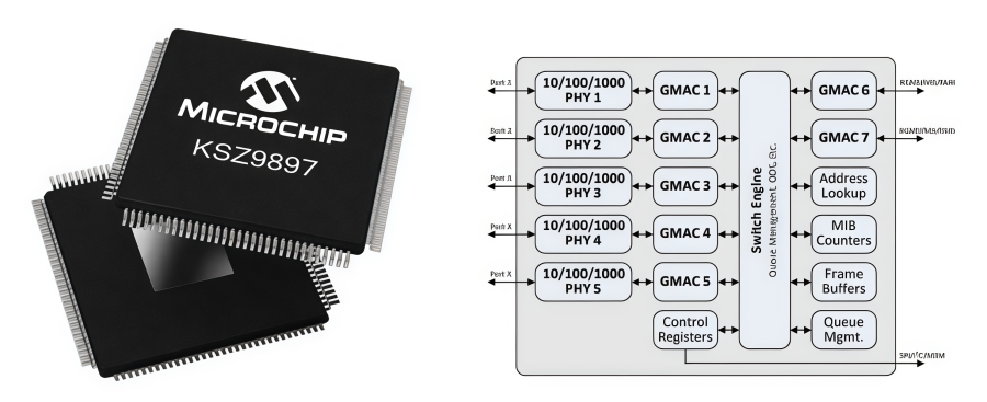
The KSZ9897RTXI is a highly integrated IEEE 802.3-compliant Layer 2 managed Gigabit Ethernet switch that combines a 7-port switch, five integrated 10BASE-Te/100BASE-TX/1000BASE-T PHYs, and two configurable MAC interfaces. The device supports RGMII, MII, and RMII interfaces, allowing flexible connection to host processors, controllers, Ethernet switches, or external PHY devices.Designed for high-performance networking applications, the KSZ9897RTXI features wire-speed Gigabit switching, VLAN, QoS, ACL filtering, traffic prioritization, and Spanning Tree support. It also provides flexible management through SPI, I²C, and MIIM interfaces, enabling easy configuration of PHY, MAC, and switch functions.KSZ9897RTXI is well suited for industrial Ethernet switches, automation systems, embedded gateways, and other advanced networking applications.(Contact us for a quote) Technical SpecificationsParameterValuePart NumberKSZ9897RTXIDescriptionIC ETHERNET SWITCH 7PORT 128TQFPManufacturerMicrochip TechnologyLead Free Status / RoHS StatusLead free / RoHS CompliantVoltage - Supply1.8V, 2.5V, 3.3VStandards10/100/1000 Base-T PHYOperating Temperature-40°C ~ 85°CFunctionSwitchMoisture Sensitivity Level (MSL)3 (168 Hours)ProtocolEthernetInterfaceI²C, SPIPackage128-TQFP-EP (14x14)Base Part NumberKSZ9897R Core Features• Switch Management Capabilities- 10/100/1000Mbps Ethernet switch basic functions: frame buffer management, address look-up table, queue management, MIB counters- Non-blocking store-and-forward switch fabric assures fast packet delivery by utilizing 4096 entry forwarding table with 256kByte frame buffer- Jumbo packet support up to 9000 bytes- Port mirroring/monitoring/sniffing: ingress and/or egress traffic to any port- MIB counters for fully-compliant statistics gathering 34 counters per port- Tail tagging mode (one byte added before FCS) support at host port to inform the processor which ingress port receives the packet and its priority- Loopback modes for remote failure diagnostics- Rapid spanning tree protocol (RSTP) support for topology management and ring/linear recovery- Multiple spanning tree protocol (MSTP) support • Five Integrated PHY Ports- 1000BASE-T/100BASE-TX/10BASE-Te IEEE 802.3- Fast Link-up option significantly reduces link-up time- Auto-negotiation and Auto-MDI/MDI-X support- On-chip termination resistors and internal biasing for differential pairs to reduce power- LinkMD® cable diagnostic capabilities for determining cable opens, shorts, and length • Two Configurable External MAC Ports- Reduced Gigabit Media Independent Interface(RGMII) v2.0- Reduced Media Independent Interface (RMII) v1.2 with 50MHz reference clock input/output option- Media Independent Interface (MII) in PHY/MAC mode • Advanced Switch Capabilities- IEEE 802.1Q VLAN support for 128 active VLAN groups and the full range of 4096 VLAN IDs- IEEE 802.1p/Q tag insertion/removal on per port basis- VLAN ID on per port or VLAN basis- IEEE 802.3x full-duplex flow control and half-duplex back pressure collision control- IEEE 802.1X access control (Port-based and MAC address based)- IGMP v1/v2/v3 snooping for multicast packet filtering- IPv6 multicast listener discovery (MLD) snooping- IPv4/IPv6 QoS support, QoS/CoS packet prioritization- 802.1p QoS packet classification with 4 priority queues- Programmable rate limiting at ingress/egress ports- Broadcast storm protection- Four priority queues with dynamic packet mapping for IEEE 802.1p, IPv4 DIFFSERV, IPv6 Traffic Class- MAC filtering function to filter or forward unknown unicast, multicast and VLAN packets- Self-address filtering for implementing ring topologies • Comprehensive Configuration Registers Access- High-speed 4-wire SPI (up to 50MHz), I2C interfaces provide access to all internal registers- MII Management (MIIM, MDC/MDIO 2-wire) Interface provides access to all PHY registers- In-band management via any of the data ports- I/O pin strapping facility to set certain register bits from I/O pins at reset time- On-the-fly configurable control registers • Power Management- Energy detect power-down mode on cable disconnect- Dynamic clock tree control- Unused ports can be individually powered down- Full-chip software power-down- Wake-on-LAN (WoL) standby power mode with PME interrupt output for system wake upon triggered events Highlightsl Non-blocking wire-speed Ethernet switching fabricl Full-featured forwarding and filtering control, including Access Control List (ACL) filteringl Full VLAN and QoS supportl Five ports with integrated 10/100/1000BASE-T PHY transceiversl Two ports with 10/100/1000 Ethernet MACs and configurable RGMII/MII/RMII interfacesl IEEE 802.1X access control supportl EtherGreen™ power management features, including low power standbyl Flexible management interface options: SPI, I2C, MIIM, and in-band management via any portl Commercial/Industrial temperature range supportl 128-pin TQFP-EP (14 x 14mm) RoHS compliant pkg(Contact us for a quote) Pin Configurations Internal Block Diagram & System ArchitectureThe KSZ9897RTXI features a highly integrated hardware architecture consisting of port transceiver units, a switch engine, and supporting functional modules. It integrates five 10/100/1000 Mbps PHYs for Ports 1–5, each paired with an independent GMAC for Ethernet frame processing. Additionally, GMAC6 and GMAC7 provide external Gigabit MAC interfaces supporting RGMII, MII, and RMII, enabling flexible connection with host processors or external PHY devices.At the center of the device, the Switch Engine manages packet forwarding, QoS, and traffic scheduling through modules such as the Address Lookup Engine, Frame Buffer, MIB Counters, and Queue Management. Device configuration is performed through control registers via SPI, I²C, or MIIM interfaces, allowing adjustment of network parameters including port settings, VLAN, and QoS. With integrated Gigabit PHYs, flexible MAC expansion, and advanced Layer 2 switching capabilities, the KSZ9897RTXI is ideal for industrial Ethernet switches, embedded gateways, and high-performance networking systems. Hardware Design ConsiderationsWhen designing with the KSZ9897RTXI, several key hardware considerations should be followed:Power Supply Design: Use separate core, I/O, and analog power rails with proper decoupling. Isolate the analog supply from the digital 3.3V rail to minimize noise and place decoupling capacitors close to each power pin.Clock and Reset: Use a 25 MHz crystal with high frequency accuracy and ensure the RESET_N signal remains low for the required delay after power-up.Ethernet Differential Routing: Route MDI differential pairs with controlled impedance, matched lengths, and adequate ESD protection to maintain signal integrity.RGMII Interface Layout: Follow the recommended impedance and termination requirements, and ensure proper clock delay or length matching based on the selected RGMII timing mode.Strap Pin Configuration: Configure all strap pins with dedicated pull-up or pull-down resistors before reset to ensure the device enters the correct operating mode.PCB Layout and Thermal Design: A 4-layer PCB is recommended. Separate digital and chassis ground where required, and connect the exposed thermal pad to the ground plane using thermal vias for effective heat dissipation. TSN and AVB Microarchitecture ManagementThe KSZ9897RTXI integrates TSN (Time-Sensitive Networking) and AVB (Audio Video Bridging) hardware features to deliver deterministic, low-latency, and highly reliable Ethernet communication. It supports 8 hardware priority queues per port, along with SP/WRR scheduling, CBS and TAS traffic shaping, and IEEE 802.1CB FRER for redundant frame transmission, ensuring efficient handling of real-time industrial and multimedia traffic. The KSZ9897RTXI-TR, which uses the same device specifications with a tape-and-reel packaging option, is suitable for automated SMT production environments requiring high-volume assembly.For precise network synchronization, the device includes a hardware timestamp engine and an IEEE 802.1AS-compatible RTC, enabling accurate PTP/gPTP time synchronization with nanosecond-level precision. To achieve optimal TSN performance, engineers should use high-speed management interfaces such as SPI or RGMII, configure hardware timestamping, and properly allocate buffer resources to ensure reliable real-time data transmission. The KSZ9897RTXI-TR provides the same TSN and AVB capabilities while offering packaging flexibility for industrial networking applications.(Contact us for a quote) Typical ApplicationsWith advanced Layer 2 switching features, multiple Gigabit ports, VLAN/QoS support, and flexible management interfaces, KSZ9897RTXIcan meet the requirements of various high-performance networking applications. 1. Stand-alone 10/100/1000 Mbps Ethernet SwitchesThe KSZ9897RTXI integrates five Gigabit PHY ports and advanced switching functions, making it suitable for standalone Ethernet switch designs. It supports wire-speed data forwarding, VLAN configuration, QoS management, and traffic prioritization to provide efficient and reliable network connections in enterprise and industrial environments. 2. VoIP Infrastructure SwitchesFor Voice over IP (VoIP) networks, low latency and stable data transmission are essential. The KSZ9897RTXI supports QoS and traffic classification features to prioritize voice packets, helping reduce delay, jitter, and packet loss for improved voice communication quality. 3. Broadband Gateways and FirewallsThe device can be integrated into broadband gateways, routers, and firewall systems that require multiple Ethernet connections. Its flexible MAC interfaces allow connection with processors or external network devices, while Layer 2 management features support efficient traffic control and network configuration. 4. Wi-Fi Access PointsThe KSZ9897RTXI is suitable for high-performance Wi-Fi access points that require Ethernet backhaul connectivity. Its Gigabit switching capability provides fast data transfer between wireless modules, processors, and wired networks, supporting stable communication in high-bandwidth applications. 5. Integrated DSL/Cable ModemsIn DSL and cable modem systems, the Ethernet switch helps manage data communication between the modem controller and connected devices. The KSZ9897RTXI provides reliable Gigabit Ethernet connectivity with low-latency switching and flexible interface options for system integration. 6. Security and Surveillance SystemsModern IP surveillance systems require stable transmission of high-resolution video streams. With Gigabit switching performance, QoS support, and reliable packet handling, the KSZ9897RTXI is well suited for IP cameras, NVR systems, and security networking equipment. 7. Industrial Control and Automation SwitchesDesigned for industrial networking applications, the KSZ9897RTXI supports reliable Ethernet communication in factory automation, PLC networks, and machine control systems. Its industrial temperature option, advanced traffic management, and robust Layer 2 features help ensure stable operation in demanding environments. 8. Networked Measurement and Control SystemsThe KSZ9897RTXI can be used in distributed measurement and control systems that require real-time data exchange between multiple devices. Its low-latency switching, VLAN support, and flexible management interfaces enable efficient communication in industrial monitoring and embedded network applications. Package Information ANDE Electronics: Your Trusted Partner in Electronic Component Sourcing At ANDE Electronics, we make getting the electronic components you need simple and fast. We work directly with top global manufacturers to provide high-quality components that have passed our strict checks, so you can count on them for your projects.We also focus on quick and consistent delivery to keep your work on schedule and avoid delays. When you need reliable and efficient electronic parts for your projects, ANDE Electronics is a partner you can trust.(Contact us for a quote)
260
26/07/10
BSS84LT1G P-Channel MOSFET: Specs, Pinout & Applications
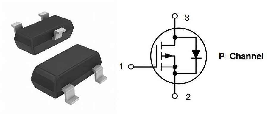
The BSS84LT1G is a P-channel enhancement-mode MOSFET featuring a -50 V drain-to-source voltage, low on-resistance, and low power consumption. It is widely used in load switching, power management, battery protection, and portable electronic devices.This article provides an overview of the BSS84LT1G, covering its key specifications, pin configuration, operating principle, typical applications, and more to help engineers better understand its characteristics and select the right device for their designs.(Contact us for a quote) What Is BSS84LT1G?The BSS84LT1G P-channel MOSFET comes in a compact SOT-23 surface-mount package and is primarily designed for low-voltage, low-current switching, logic-level translation, and high-side load control. With a maximum drain-to-source voltage (VDS) of -50 V and a continuous drain current (ID) of up to -130 mA, it is well suited for handling low-power control signals.In addition, the device can be fully turned on with a relatively low gate drive voltage, and some versions feature integrated ESD protection. The BSS84LT1G is widely used for logic-level shifting between different voltage domains, such as 3.3 V and 5 V systems, as well as for power switching of low-power loads controlled by microcontrollers (MCUs). BSS84LT1G Operating PrincipleThe BSS84LT1G is controlled by the voltage between its gate (G) and source (S) terminals (VGS). When the gate voltage is lower than the source voltage, making VGS negative and below the gate-to-source threshold voltage (VGS(th)), the MOSFET turns on, allowing current to flow from the source to the drain. When the gate voltage approaches or equals the source voltage, the MOSFET turns off, cutting off the current to the load.Since P-channel MOSFETs are typically placed on the positive power rail, the BSS84LT1G is widely used in high-side switching applications. By simply changing the gate voltage, a microcontroller (MCU) or control circuit can switch power to the downstream load on or off without requiring a complex gate driver. BSS84LT1G SpecificationsParameterValuePart NumberBSS84LT1GDescriptionMOSFET P-CH 50V 130MA SOT-23Lead Free Status / RoHS StatusLead free / RoHS CompliantVgs (Max)±20VCurrent - Continuous Drain (Id) @ 25°C130mA (Ta)Operating Temperature-55°C ~ 150°C (TJ)Rds On (Max) @ Id, Vgs10 Ohm @ 100mA, 5VFET TypeP-ChannelDrain to Source Voltage (Vdss)50VMounting TypeSurface MountVgs(th) (Max) @ Id2V @ 250µAPower Dissipation (Max)225mW (Ta)Moisture Sensitivity Level (MSL)1 (Unlimited)Drive Voltage (Max Rds On, Min Rds On)5VInput Capacitance (Ciss) (Max) @ Vds30pF @ 5VPackageSOT-23-3 (TO-236)Base Part NumberBSS84(Contact us for a quote) BSS84LT1G Pin ConfigurationPin 1 – Gate (G)The Gate is the control terminal of the MOSFET and has a very high input impedance, requiring almost no input current. The BSS84LT1G turns on when the gate voltage is pulled below the source voltage, making VGS sufficiently negative. When the gate voltage approaches the source voltage, the MOSFET turns off. Pin 2 – Source (S)The Source is the current input terminal and is typically connected to the positive power supply (VCC) in P-channel MOSFET applications. Because of this configuration, the BSS84LT1G is widely used for high-side load switching. Pin 3 – Drain (D)The Drain is connected to the load. When the MOSFET is turned on, current flows from the Source to the Drain, supplying power to the load. When the device is off, the current path is interrupted, disconnecting the load from the power source. BSS84LT1G Design ConsiderationsIn practical circuit design, understanding and optimizing the following six factors can help ensure the long-term reliability of the BSS84LT1G.l Gate Drive Voltage: The threshold voltage (VGS(th)) is -1 V to -2 V. For full turn-on, ensure the gate voltage reaches -4.5 V or -10 V relative to the source. In low-voltage systems (e.g., 1.8 V), incomplete turn-on may increase power dissipation.l PCB Thermal Layout: The SOT-23 package has limited heat dissipation (up to 225 mW). Use larger copper areas connected to the Drain pin and avoid placing heat-generating components too close together.l RDS(on) Selection: With an RDS(on) of approximately 3.5–5 Ω, calculate conduction loss (P = I² × RDS(on)) and verify that the resulting voltage drop does not affect the load.l Switching Frequency: The low input capacitance (Ciss ≈ 45 pF) enables fast switching. At high PWM frequencies, switching losses increase, so a small gate resistor can help reduce ringing.l Current Limitation: The maximum continuous drain current is approximately -130 mA. It is intended for low-power loads such as signal switching, LEDs, or relays, not motors or other high-current devices.l Reverse Polarity Considerations: The device includes an intrinsic body diode. In reverse-polarity or power-switching circuits, correct Source and Drain orientation is essential, as the body diode can conduct even when the MOSFET is turned off. BSS84LT1G Featuresl SOT−23 Surface Mount Package Saves Board Space l BV Prefix for Automotive and Other Applications Requiring Unique Site and Control Change Requirements; AEC−Q101 Qualified and PPAP Capable l These Devices are Pb−Free and are RoHS Compliantl P-Channel Enhancement-Mode MOSFET for High-Side Switching Applicationsl Low On-State Resistance Reduces Conduction Lossesl Low Gate Threshold Voltage for Easy Logic-Level Drivel Fast Switching Performance with Low Input Capacitancel Low Leakage Current Improves Power Efficiency in Standby Model Suitable for Load Switching, Power Management, and Voltage Level Translation Applicationsl Available in Tape and Reel Packaging for Automated Assembly(Contact us for a quote) BSS84LT1G Applications1. Load SwitchingBSS84LT1G is commonly used as a high-side load switch in low-power electronic systems. Its P-channel MOSFET structure allows the device to control power delivery to downstream components with simple gate drive circuits. It is suitable for switching small loads such as LEDs, sensors, relays, and other peripheral devices. 2. Power Management CircuitsWith low power consumption and compact SOT-23 packaging, BSS84LT1G is widely applied in power management designs. It can be used for power distribution, power gating, and standby power control in battery-powered and embedded systems to improve energy efficiency. 3. Battery-Powered DevicesBSS84LT1G is suitable for portable devices that require efficient power control. It can be integrated into battery management circuits to disconnect or reconnect power paths, helping reduce standby current and extend battery life in devices such as handheld electronics and wearable products. 4. Logic Level TranslationThe device can be used for voltage level shifting between different logic systems, such as 3.3 V and 5 V interfaces. By controlling the MOSFET switching state, BSS84LT1G helps achieve reliable signal conversion in microcontroller-based systems and communication circuits. 5. Embedded Systems and Consumer ElectronicsDue to its small size and easy integration, BSS84LT1G is commonly used in compact electronic devices. Typical applications include MCU-controlled power switches, smart home devices, portable instruments, and other low-power consumer electronics. 6. Industrial Control and Interface CircuitsBSS84LT1G can also be applied in industrial control systems for low-current switching tasks. It is suitable for controlling indicator circuits, interface modules, and auxiliary power supplies where compact size and reliable switching performance are required. BSS84LT1G Package ANDE Electronics: Your Trusted Partner in Electronic Component Sourcing At ANDE Electronics, we make getting the electronic components you need simple and fast. We work directly with top global manufacturers to provide high-quality components that have passed our strict checks, so you can count on them for your projects.We also focus on quick and consistent delivery to keep your work on schedule and avoid delays. When you need reliable and efficient electronic parts for your projects, ANDE Electronics is a partner you can trust.(Contact us for a quote)
262
26/07/06
NEC NL3224BC35-20 LCD Display Features & Applications
NL3224BC35-20 is a 5.5-inch industrial TFT LCD display module developed by NEC LCD Technologies. It features a-Si TFT-LCD technology with a 320 × 240 (QVGA) resolution. The module uses a CCFL backlight and supports a digital RGB interface, making it suitable for industrial PCs, control terminals, POS systems, and other industrial applications.This article provides a comprehensive overview of the NL3224BC35-20, including its specifications, key features, applications, datasheet, and installation and handling precautions. It is designed to help engineers, system designers, and buyers quickly understand the display module and support industrial equipment development and maintenance. NL3224BC35-20 SpecificationsBelow is the key specification table of the NL3224BC35-20, including screen size, resolution, brightness, interface, backlight, etc., which can help evaluate its compatibility and overall performance for industrial applications.Parameter ValueBrandNECModelNL3224BC35-20Size5.5"CompositionLCMResolution320(RGB)×240, QVGA 72PPILuminance400 cd/m² (Typ.)Contrast Ratio400 : 1 (Typ.) (TM)Viewangle55/55/50/40Color Depth262K 50% NTSCLight SourceCCFL [2 pcs] , 40K hours , W/O DriverInterface TypeCMOS (1 ch, 6-bit) , 33 pins ConnectorActive Area116.4(W)×88.5(H) mmPixel FormatRGB Vertical StripeFrame Rate60HzTouchscreenWithoutVoltage Supply3.3/5.0V (Typ.)(VCC)Weight210/220g (Typ./Max.)Outline Size134(H)×104.5(V)×13(D) mmVibration Level3.0G (29.4 m/s²)Max RatingsOperating Temperature: -10 ~ 70 °C ; Storage Temperature: -30 ~ 80 °C (Contact us for a quote) NL3224BC35-20 Structure and PrincipleNL3224BC35-20 module is composed of the amorphous silicon thin film transistor liquid crystal display (a-Si TFT LCD) panel structure with driver LSIs for driving the TFT (Thin Film Transistor) array and a backlight unit. The a-Si TFT LCD panel structure injects liquid crystal material into a narrow gap between the TFT array glass substrate and a color-filter glass substrate. Color (Red, Green, Blue) data signals from a host system (e.g., PC, signal generator, etc.) are modulated into the best form for the active matrix system by a signal processing board and sent to the driver LSIs, which drive the individual TFT arrays.The TFT array as an electro-optical switch, regulates the amount of transmitted light from the backlight assembly when it is controlled by data signals. Color images are created by regulating the amount of transmitted light through the TFT array of red, green and blue dots. NL3224BC35-20 Key FeaturesThe NL3224BC35-20 offers high brightness, a wide color gamut, wide viewing angles, and low reflectance, making it well suited for industrial control systems, HMIs, embedded devices, and other industrial display applications.l High luminance: It delivers a high brightness level (typically up to 400cd/m²).l Wide color gamut: It covers a broader color spectrum compared to standard legacy displays (approx. 40% NTSC).l Low reflection: The screen surface is treated with an anti-glare and hard coating.l 6-bit digital RGB signals: Utilizing a standard 6-bit parallel TTL/RGB interface, it supports up to 262K colors.l Reversible-scan direction: It features pin-controlled image flipping (horizontal and vertical).l Edge light type: The backlight configuration is positioned along the edge of the panel.l Replaceable lamp for backlight unit (Inverter-less)· l Acquisition product for UL/c-UL (File number: E170632).(Contact us for a quote) NL3224BC35-20 CMOS/TTL InterfaceIn traditional parallel CMOS/TTL (RGB 6-bit) interfaces, efficient image transmission relies on tight coordination of the clock (CLK), data enable (DE), and horizontal/vertical sync signals (Hsync/Vsync). CLK acts as the system core, latching and transferring one pixel of RGB data per cycle. Hsync and Vsync generate pulses to mark the start of a new line and frame, resetting the display scan position. DE defines the valid display window—data is only shown when DE is active, while other periods are blanking intervals.When interfacing with modern high-integration MCUs (e.g., ARM with LTDC) or FPGAs, hardware wiring is simple: connect the upper 6 bits of RGB data lines (e.g., R[7:2]) to the display, with control signals (CLK, DE, etc.) directly linked. On the software side, MCUs only need to configure pixel clock, signal polarity, and porch timings in registers, after which hardware handles driving automatically. For FPGAs, line and frame counters are implemented in logic to generate Hsync, Vsync, and DE signals under clock control, while reading framebuffer data and outputting it to drive the display. NL3224BC35-20 Typical ApplicationsThe NL3224BC35-20 is widely used in industrial and embedded display systems, serving as a reliable display solution across a wide range of applications. 1. Industrial PCThis model is commonly used in industrial-grade computer systems and is suitable for devices requiring stable human–machine interaction interfaces. Its compact structure allows easy integration into control cabinets or embedded terminals.l Factory automation PCsl Data acquisition terminalsl Edge computing boxes 2. Control System Display TerminalThe NL3224BC35-20 is suitable for HMI display units in various industrial control systems, delivering stable performance even in complex industrial environments.l PLC control panelsl Process monitoring terminalsl Equipment status displays 3. POS TerminalIt is widely used in retail and service industry POS systems, providing clear transaction interfaces and supporting long-term stable operation.l Supermarket checkout machinesl Restaurant ordering systemsl Self-service payment terminals 4. Industrial HMI PanelThis panel is commonly used in industrial human–machine interfaces requiring real-time monitoring and operation, supporting both touchscreen and button-based control integration.l Production line HMI panelsl Equipment control touchscreensl Factory monitoring interfaces 5. Measurement & Testing EquipmentIt is used in various testing and inspection instruments as a display module, ensuring stable and clear visualization of data and waveforms.l Oscilloscope displaysl Environmental testing instrumentsl Electronic measurement equipment(Contact us for a quote) NL3224BC35-20 Outline DrawingsThe outline drawing of the NL3224BC35-20 LCD display illustrates the module's overall dimensions, active display area, mounting hole locations, and interface positions, providing essential mechanical information for system design and integration. NL3224BC35-20 DatasheetYou can refer to the official datasheet of NL3224BC35-20 LCD to see more details below: Datasheet PDF Handling Precautions1) Take hold of both ends without touching the circuit board when the customer pulls out products (LCD modules) from the inner packing box. If the customer touches it, products may be broken down or out of adjustment, because of stress on mounting parts.2) Do not hook cables or pull connection cables, such as flexible cables, and so on, for fear of damage.3) If the customer puts down the product temporarily, the product is put on a flat surface as a display and then turned off.4) Take the measures of electrostatic discharge, such as an earth band, ionic shower, and so on, when the customer deals with the product, because products may be damaged by electrostatic.5) The torque for mounting screws must never exceed 0.29 N · m. Higher torque values might result in distortion of the bezel.6) Do not press or rub on the sensitive display surface. If the customer cleans the panel surface, NECCorporation recommends using the cloth with an ethanolic liquid, such as a screen cleaner for LCD.7) Do not push-pull the interface connectors while the product is working, because the wrong power sequence may damage the product. ANDE Electronics: Reliable LCD Display SolutionsAs a professional display supplier, Ande Electronics is committed to providing LCD modules that meet modern application needs.We offer not only high-quality display products but also reliable technical support and flexible purchasing options. Our experienced engineering team works closely with customers to provide guidance on module selection, integration, and optimization.Choosing Ande Electronics, then engineers and manufacturers will gain a partner focused on quality, innovation, and efficiency.(Contact us for a quote)
137