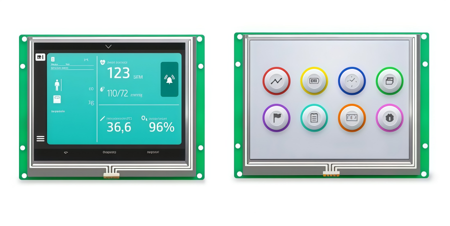
The AUO G104STN01.0 is a 10.4-inch a-Si TFT-LCD display module product. It integrates a complete display solution, including the TFT-LCD panel, driver and power supply circuits, and a WLED backlight system.
The panel supports an SVGA resolution of 800 × 600 pixels and can display up to 16.2 million colors (RGB 8-bit) or 262K colors (RGB 6-bit), providing clear and stable image performance for embedded display systems. In addition, the module includes an integrated LED driver board, and the LED backlight unit is replaceable, making maintenance and long-term operation more convenient.
This article will introduce the key specifications, structural design, and typical application scenarios of G104STN01.0.
G104STN01.0 Core Specifications
We will focus on its core specifications to help you better understand the display panel’s performance characteristics and suitability for industrial applications. The table below summarizes the key technical parameters of the G104STN01.0.
Parameter | Value |
Brand | |
Model | G104STN01.0 |
Size | 10.4" |
Composition | LCM |
Resolution | 800(RGB)×600, SVGA 96PPI |
Luminance | 400 cd/m² (Typ.) |
Contrast Ratio | 700:1 (Typ.) (TM) |
Viewangle | 80/80/60/70 |
Color Depth | 262K/16.2M 50% NTSC |
Light Source | 8S2P WLED , 50K hours , With LED Driver |
Interface Type | LVDS (1 ch, 6/8-bit) , 20 pins Connector |
Active Area | 214.8(W)×162.7(H) mm |
Pixel Format | RGB Vertical Stripe |
Frame Rate | 60Hz |
Touchscreen | Without |
Voltage Supply | 3.3V (Typ.) |
Weight | 365g (Typ.) |
Outline Size | 243×184×7 (H×V×D) |
Max Ratings | Operating Temperature: -30 ~ 80 °C ; Storage Temperature: -30 ~ 80 °C |
Refer to G104STN01.0 Datasheet PDF
G104STN01.0 LCD Panel Structure Overview
The G104STN01.0 consists of several core modules working together, each performing a specific function. Its overall structure can generally be divided into four key parts: the TFT-LCD display panel, backlight unit, driver circuitry, and signal interface.
TFT-LCD Display Panel
This component is the core of the entire display system and adopts an amorphous silicon (a-Si TFT) thin-film transistor structure. Each pixel is controlled by an individual TFT transistor. By adjusting the alignment of liquid crystal molecules, the panel changes the light transmittance, thereby producing different gray levels and colors.
Backlight Unit
Since liquid crystals do not emit light by themselves, a backlight module is required to provide illumination. The G104STN01.0 uses an LED backlight system. With the help of a light guide plate and diffusion films, the light is evenly distributed across the entire display area, ensuring uniform brightness and clear, stable images.
Driver Circuit
The driver circuit mainly consists of a gate driver (row driver IC) and a source driver (column driver IC). Their role is to control pixel scanning and refreshing. The gate driver activates the pixel rows sequentially, while the source driver adjusts the voltage of each pixel according to the input signal, thereby controlling the light transmittance of the liquid crystal.
Signal Interface
This module receives video signals from the main control board. The G104STN01.0 typically uses an LVDS (Low Voltage Differential Signaling) interface for data transmission. This interface enables stable and efficient communication between the display panel and the system controller.
G104STN01.0 Interface and Electrical Performance
The electrical performance and signal processing capabilities of the G104STN01.0 are the core pillars of its long-term stability. This section provides an in-depth analysis of the module's interface and electrical characteristics, serving as a critical technical reference for integration engineers.
1. LVDS (1 ch, 6/8-bit) 20-pin Interface Overview
The module uses an LVDS (1 ch, 6/8-bit) signal interface, facilitating data transmission via a standard 20-pin connector. This single-channel design ensures real-time synchronization at 800x600 (SVGA) resolution. By leveraging differential signaling technology, it delivers superior signal stability, effectively minimizing electromagnetic interference (EMI) in complex industrial environments.
G104STN01.0 20-Pin Interface Pinout
Pin No. | Symbol | Description |
1 | VCC | Logic Power Supply (+3.3V Typ.) |
2 | VCC | Logic Power Supply (+3.3V Typ.) |
3 | GND | Ground |
4 | GND | Ground |
5 | RX0- | LVDS Differential Data Input (Pair 0-) |
6 | RX0+ | LVDS Differential Data Input (Pair 0+) |
7 | GND | Ground |
8 | RX1- | LVDS Differential Data Input (Pair 1+) |
9 | RX1+ | LVDS Differential Data Input (Pair 1+) |
10 | GND | Ground |
11 | RX2- | LVDS Differential Data Input (Pair 2-) |
12 | RX2+ | LVDS Differential Data Input (Pair 2+) |
13 | GND | Ground |
14 | CLK- | LVDS Differential Clock Input (-) |
15 | CLK+ | LVDS Differential Clock Input (+) |
16 | GND | Ground |
17 | RX3- | LVDS Differential Data Input (Pair 3-) |
18 | RX3+ | LVDS Differential Data Input (Pair 3+) |
19 | GND | Ground |
20 | SEL68 | LVDS 6/8-bit Selection (High: 6-bit / Low or NC: 8-bit) |
2. Integrated Driving Solution (Built-in LED Driver)
To further reduce system integration complexity, the panel features a Built-in LED Driver. By integrating the constant-current control circuitry directly onto the T-CON board, this design not only simplifies system architecture but also significantly reduces the count of external components, thereby lowering the routing pressure on the main PCB.
3. 50,000 to 70,000 Hours Operational Reliability
The backlight of this module boasts an impressive lifespan of 50,000 to 70,000 hours (typical value). Even under high-intensity 24/7 continuous operation, the backlight brightness decay remains slow, significantly reducing the Total Cost of Ownership (TCO) for end-users.
4. Voltage Requirements and Energy Efficiency
In terms of power management, the G104STN01.0 maintains extremely low and stable voltage requirements. Its core logic power supply is typically 3.3V (Typ.), which, combined with optimized driving algorithms, achieves an excellent low-power consumption mode, ideal for heat-sensitive or battery-powered industrial devices.
G104STN01.0 Application Fields
With its 10.4-inch size, SVGA resolution, and reliable TFT-LCD structure, the G104STN01.0 is commonly suitable for a wide range of industrial and professional display scenarios.
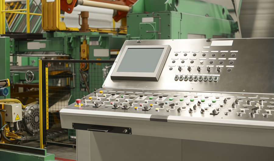
1. Industrial Automation and Control Systems
In industrial automation environments, display panels are widely used as human-machine interfaces (HMI) to monitor and control production processes.
l PLC control panels
l Industrial HMI terminals
l CNC machine interfaces
2. Medical and Diagnostic Equipment
Many medical devices require compact displays to show system data, monitoring results, and control menus. The G104STN01.0 can provide clear and consistent visual output for medical staff.
l Patient monitoring systems
l Portable diagnostic instruments
l Medical imaging control panels
3. Test and Measurement Instruments
The G104STN01.0 can also serve as a professional measurement display to present waveforms, system parameters, or test results in real time.
l Oscilloscopes and signal analyzers
l Power testing equipment
l Network testing instruments
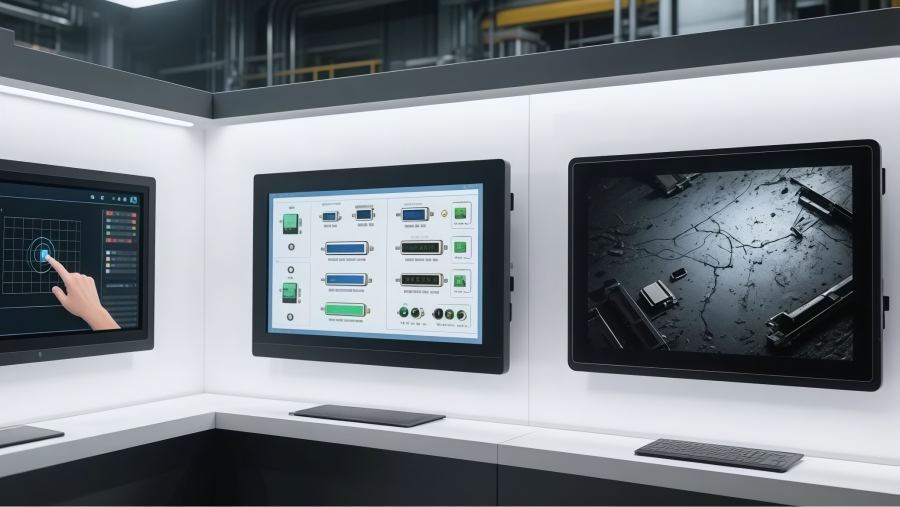
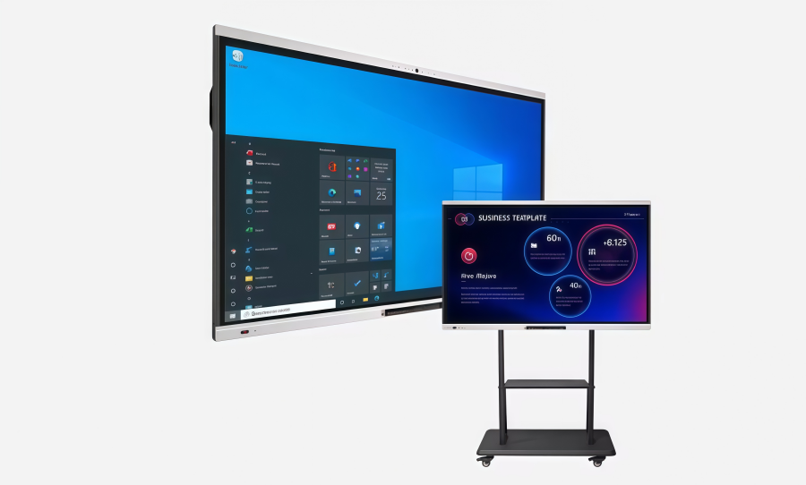
4. Embedded Systems and Industrial Terminals
Many embedded systems require reliable displays for configuration, monitoring, and data interaction. The G104STN01.0 can be integrated into various industrial terminals and embedded computing systems.
l Industrial computers
l Self-service kiosks
l Smart energy management systems
Operating Precautions
1. Avoid scratching the front polarizer surface.
2. Turn off the power before connecting or disconnecting the input connector.
3. Wipe off water immediately to prevent discoloration or spots.
4. Clean the panel surface with soft cloth or absorbent cotton only.
5. Handle carefully, as the glass panel may crack if dropped or hit.
6. Ground yourself before handling to prevent ESD damage.
7. Do not disassemble or modify the module.
8. Do not press the reflector sheet on the back of the module.
9. When placing the module back into the package, press gently on the ends of the LED bar edge, not the center.
10. Do not tilt or rotate the signal interface connector during insertion or removal.
11. Avoid twisting or bending the module during installation or use.
12. Power supply must comply with Limited Power Source requirements (IEC60950 / UL1950).
13. Extreme temperatures may affect brightness, response time, and lamp ignition voltage.
14. Long operation at low temperatures may reduce brightness and shorten lamp life.
15. Specification data applies when the module is used in landscape orientation.
16. Avoid displaying static images for long periods to prevent image sticking.
ANDE Electronics: Reliable LCD Display Solutions

As a professional display supplier, Ande Electronics is committed to providing LCD modules that meet modern application needs.
We offer not only high-quality display products but also reliable technical support and flexible purchasing options. Our experienced engineering team works closely with customers to provide guidance on module selection, integration, and optimization.
Choosing Ande Electronics, then engineers and manufacturers will gain a partner focused on quality, innovation, and efficiency.