STM8S103F3P6 Description
The STM8S103F3P6 is an 8-bit microcontroller (MCU) from STMicroelectronics, based on the STM8 core. It features high performance, low power consumption, and a rich set of peripheral interfaces. The MCU integrates Flash memory, SRAM, EEPROM, as well as multiple timers, ADCs, USART, and I²C/SPI interfaces.
The chip operates at a maximum clock frequency of 16 MHz and supports various low-power modes for efficient energy management. Its compact package facilitates space-saving designs and provides multiple GPIO channels for easy peripheral expansion. The STM8S103F3P6 is commonly used in motor control, sensor interfaces, display driving, and simple communication systems.
STM8S103F3P6 Key Specs
Parameter | Value |
Part Number | STM8S103F3P6 |
Description | IC MCU 8BIT 8KB FLASH 20TSSOP |
Lead Free Status / RoHS Status | Lead free / RoHS Compliant |
Operating Temperature | -40°C ~ 85°C (TA) |
EEPROM Size | 640 x 8 |
Voltage - Supply (Vcc/Vdd) | 2.95 V ~ 5.5 V |
Connectivity | I²C, IrDA, LINbus, SPI, UART/USART |
Data Converters | A/D 5x10b |
Program Memory Size | 8KB (8K x 8) |
Package | 20-TSSOP(0.173, 4.40mm Width) |
Core Size | 8-Bit |
Speed | 16MHz |
Moisture Sensitivity Level (MSL) | 1 (Unlimited) |
Program Memory Type | FLASH |
Number of I/O | 16 |
Base Part Number | STM8S103 |
STM8S103F3P6 Pinout

Pin 1 (VCAP) – Connects to the internal voltage regulator capacitor.
Pin 2 (VDDA) – Analog power supply.
Pin 3 (VSSA) – Analog ground.
Pin 4 (PA1) – General-purpose I/O and ADC input.
Pin 5 (PA2) – General-purpose I/O, ADC input, or USART TX.
Pin 6 (PA3) – General-purpose I/O, ADC input, or USART RX.
Pin 7 (PB4) – General-purpose I/O or timer output.
Pin 8 (PB5) – General-purpose I/O, I²C or SPI interface.
Pin 9 (VDD) – Digital power supply.
Pin 10 (VSS) – Ground.
Pin 11 (PC3) – General-purpose I/O, timer, or external interrupt.
Pin 12 (PC2) – General-purpose I/O, timer, or external interrupt.
Pin 13 (PC1) – General-purpose I/O, I²C, SPI, or timer.
Pin 14 (PC0) – General-purpose I/O, I²C, SPI, or timer.
Pin 15 (PD2) – General-purpose I/O, timer, or external interrupt.
Pin 16 (PD3) – General-purpose I/O, timer, or external interrupt.
Pin 17 (PD4) – General-purpose I/O, timer, or external interrupt.
Pin 18 (PD5) – General-purpose I/O, timer, or external interrupt.
Pin 19 (RESET) – Reset input.
Pin 20 (NRST) – External reset or debug interface.
Note: Many pins are multifunctional and can be configured according to your application. Refer to the STM8S103F3P6 datasheet for detailed usage.
STM8S103F3P6 Features
Core
• 16 MHz advanced STM8 core with Harvard architecture and 3-stage pipeline
• Extended instruction set
Memories
• Program memory: 8 Kbyte Flash; data retention 20 years at 55 °C after 10 kcycle
• Data memory: 640 byte true data EEPROM; endurance 300 kcycle
• RAM: 1 Kbyte
Clock, reset and supply management
• 2.95 to 5.5 V operating voltage
• Flexible clock control, 4 master clock sources
– Low power crystal resonator oscillator
– External clock input
– Internal, user-trimmable 16 MHz RC
– Internal low-power 128 kHz RC
• Clock security system with clock monitor
• Power management:
– Low-power modes (wait, active-halt, halt)
– Switch-off peripheral clocks individually
• Permanently active, low-consumption poweron and power-down reset
Interrupt management
• Nested interrupt controller with 32 interrupts
• Up to 27 external interrupts on 6 vectors
Timers
• Advanced control timer: 16-bit, 4 CAPCOM channels, 3 complementary outputs, dead-time insertion and flexible synchronization
• 16-bit general purpose timer, with 3 CAPCOM channels (IC, OC or PWM)
• 8-bit basic timer with 8-bit prescaler
• Auto wake-up timer
• Window watchdog and independent watchdog timers
Communication interfaces
• UART with clock output for synchronous operation, SmartCard, IrDA, LIN master mode
• SPI interface up to 8 Mbit/s
• I2C interface up to 400 kbit/s
Analog to digital converter (ADC)
• 10-bit, ±1 LSB ADC with up to 5 multiplexed channels, scan mode and analog watchdog
I/Os
• Up to 28 I/Os on a 32-pin package including 21 high sink outputs
• Highly robust I/O design, immune against current injection
STM8S103F3P6 Block Diagram

STM8S103F3P6 Applications
Motor Control
The STM8S103F3P6 can be used to drive and control DC motors, stepper motors, and small servo systems. It achieves precise speed and position control through timers and PWM output.
Sensor Interfaces
It can acquire signals from various sensors, such as temperature, light, pressure, and distance sensors, and process the data through ADC or digital interfaces for transmission and analysis.
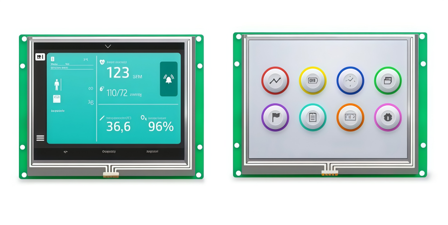
Display Driving
This MCU can drive LCDs, LED matrices, or other small display modules for status indication or information display. It supports multiple display control methods.
Automotive Electronics
The STM8S103F3P6 is widely used in small in-vehicle control systems, such as dashboards, window control, fan regulation, and lighting management, providing high reliability and low-power operation.
Industrial Control
In industrial automation equipment, it performs data acquisition, control logic processing, and signal output, making it suitable for small controllers and embedded monitoring applications.
Simple Communication Systems
With its UART, I²C, or SPI interfaces, the STM8S103F3P6 enables data communication between devices, facilitating system integration and expansion.
Home Appliance Control
It is suitable for key scanning, timer control, and status management in smart appliances, helping achieve intelligent operation and efficient energy management.
STM8S103F3P6 vs. STM8S003F3P6
When comparing the STM8S103F3P6 and the STM8S003F3P6, you are looking at two microcontrollers that are pin-to-pin compatible and share the same core architecture. While they appear identical in basic specifications, their primary differences lie in EEPROM endurance and data retention reliability, which defines their respective market positioning.
Here is a core specification comparison:
Feature | ||
Core | 16MHz STM8 Core | 16MHz STM8 Core |
Flash(Program Memory) | 8 KB | 8 KB |
RAM | 1 KB | 1 KB |
Data EEPROM | 640 Bytes | 128 Bytes |
EEPROM Endurance | 300k Write Cycles | 100k Write Cycles |
Data Retention | 20 Years (at 55°C) | 20 Years (at 55°C) |
Package | TSSOP20 | TSSOP20 |
STM8S103F3P6 Arduino
Integrating the STM8S103F3P6 into the Arduino IDE is a shortcut to achieving low-cost, small-form-factor embedded solutions. By installing the Sduino or STM8duino extension packages, developers can continue using the familiar Arduino syntax to drive this 8-bit MCU, making it ideal for lightweight tasks such as sensor data collection or PWM control.
In terms of hardware connectivity, the key to using the STM8S103F3P6 with the Arduino environment is the ST-Link V2 programmer. Unlike standard Arduinos that use serial (UART) burning, the STM8 utilizes the SWIM (Single Wire Interface Module) protocol for firmware uploads. Once configured, you can install the corresponding support packages via the Arduino Board Manager to enable one-click compilation and downloading.
ANDE Electronics: Your Trusted Partner in Electronic Component Sourcing

At ANDE Electronics, we make getting the electronic components you need simple and fast. We work directly with top global manufacturers to provide high-quality components that have passed our strict checks, so you can count on them for your projects.
We also focus on quick and consistent delivery to keep your work on schedule and avoid delays. When you need reliable and efficient electronic parts for your projects, ANDE Electronics is a partner you can trust.