LM2903M Overview
The LM2903M is a dual-voltage comparator chip that integrates two independent comparator circuits, capable of comparing two input voltages in real time and outputting a corresponding logic signal. It is widely used for voltage detection, threshold judgment, and waveform shaping. With features such as low power consumption, low offset voltage, and a wide operating voltage range, it is especially suitable for portable devices, battery-powered systems, power management, and analog signal processing applications.
In terms of performance, the LM2903M supports both single-supply (+2V to +36V) and dual-supply (±1V to ±18V) operation, providing strong flexibility in circuit design. Its low power consumption (about 1mW per comparator at +5V), wide input common-mode range including ground, and low bias currents (25nA) ensure high-precision, low-noise performance. With an output saturation voltage of 250mV at 4mA load, the chip can efficiently drive loads while maintaining stability and reliability.
LM2903M Specification
Parameter | Value |
Part Number | LM2903M |
Description | IC COMPARATOR DUAL VOLT 8-SOIC |
Lead Free Status / RoHS Status | Contains lead / RoHS non-compliant |
Manufacturer Standard Lead Time | 8 Weeks |
Type | General Purpose |
Mounting Type | Surface Mount |
Operating Temperature | -40°C ~ 85°C |
Meta Part Number | 296-39001-5-ND |
Base Part Number | LM2903 |
Package / Case | 8-SOIC |
Voltage - Supply, Single/Dual (±) | 2 V ~ 36 V, ±1 V ~ 18 V |
Output Type | CMOS, DTL, ECL, MOS, Open-Collector, TTL |
Current - Output (Typ) | 16mA @ 5V |
Current - Input Bias (Max) | 0.25µA @ 5V |
Voltage - Input Offset (Max) | 7mV @ 30V |
Current - Quiescent (Max) | 2.5mA |
Number of Elements | 2 |
Moisture Sensitivity Level (MSL) | 1 (Unlimited) |
Packaging | Tube |
Something About LM2903M/NOPB
The /NOPB suffix indicates that this version is manufactured with a lead-free, RoHS-compliant package, making it suitable for modern, environmentally conscious production standards. Thanks to its combination of precision, versatility, and eco-friendly compliance, the LM2903M/NOPB is widely used in automotive electronics, industrial control systems, and consumer devices.
LM2903M Pin Configuration

OUTPUT A - The output for comparator, channel A.
INVERTING INPUT A - The inverting input for comparator, channel A.
NON-INVERTING INPUT A - The non-inverting input for comparator, channel A.
GND - Ground connection.
NON-INVERTING INPUT B - The non-inverting input for comparator, channel B.
INVERTING INPUT B - The inverting input for comparator, channel B.
OUTPUT B - The output for comparator, channel B.
V+ - Positive power supply voltage.
LM2903M Advantages
Wide Supply Voltage: 2.0 V to 36 V
Single or Dual Supplies: ±1.0 V to ±18 V
Very Low Supply Current Drain (0.4 mA)
Low Input Biasing Current: 25 nA
Low Input Offset Current: ±5 nA
Maximum Offset voltage: ±3 mV
Input Common-Mode Voltage Range Includes Ground
Differential Input Voltage Range Equal to the Power Supply Voltage
Low Output Saturation Voltage: 250 mV at 4 mA
Output Voltage Compatible with TTL, DTL, ECL, MOS and CMOS logic systems
See AN-1112 (SNVA009) for DSBGA Considerations
High Precision Comparators
Reduced VOS Drift Over Temperature
Eliminates Need for Dual Supplies
Allows Sensing Near Ground
Compatible with All Forms of Logic
Power Drain Suitable for Battery Operation
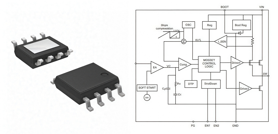
LM2903M Simplified Schematic

This diagram shows a simplified internal circuit schematic of the LM2903M. As you can see, it's primarily made up of an input differential pair (Q1, Q2, Q3, Q4), a current source, an output stage (Q6, Q7, Q8), and a biasing circuit.
The positive and negative inputs are connected to the differential amplifier. Using a current mirror and a constant current source, the circuit performs the voltage comparison function. When the positive input voltage is higher than the negative input, the conduction state of the differential pair changes. This drives the subsequent transistors, which in turn determines whether the output is a high or low level.
The LM2903M's output stage uses an open-collector structure (Q6, Q7, Q8). This means it can only pull the output to a low level. To get a stable high-level signal, you'll need an external pull-up resistor. This design offers flexibility and low power consumption while being compatible with various logic levels.
LM2903M Application Fields
1. Power Management
The LM2903M is widely used in power management circuits for over-voltage protection, under-voltage protection, and battery level detection. When a voltage goes above or below a set value, the comparator outputs a signal to trigger a protection circuit, preventing device damage or system instability.
Example:
In a laptop power module, the LM2903M can monitor battery voltage to prevent overcharging or over-discharging, which extends battery life and improves system safety.
2. Signal Processing
For signal processing, the LM2903M can be used to compare and determine voltage signals, such as for waveform shaping, window comparison, and trigger circuits. Its low power consumption and fast response make it suitable for applications requiring high-precision signal control.
Example:
In a sensor circuit, the LM2903M can compare an analog signal to a threshold, enabling functions like temperature alarms or light-intensity detection triggers.
3. Industrial Automation and Control
The LM2903M is suitable for industrial automation and control systems that require precise monitoring and logic control. It helps equipment react quickly to abnormal conditions, ensuring production safety and efficiency.
Example:
In a factory assembly line, the LM2903M can be part of an over-current detection circuit for a motor. When the current exceeds a threshold, it can immediately shut down the motor to prevent mechanical damage.
4. Battery-Powered Applications
Thanks to its low-power design, the LM2903M is an excellent fit for battery-powered portable devices. In these applications, it ensures accurate signal processing and comparison without significantly increasing power consumption.
Example:
In wearable devices, the LM2903M can be used as part of a voltage detection circuit to monitor battery levels in real-time and alert the user to charge the device.
5. Motor Control
In motor control systems, the LM2903M can detect voltage, current, and position feedback signals to enable speed control, overload protection, and fault detection. Its fast response makes motor operation safer and more efficient.
Example:
In a fan control circuit, the LM2903M can compare a motor's feedback signal to a set value, adjusting the motor speed to maintain stable operation and prevent overload.
How to Test LM2903M?
1. Visual Inspection
First, check the chip for any obvious physical damage or cracks. If there are signs of physical harm, the chip is likely already broken.
2. Test the Power Supply Voltage Range
Use an adjustable power supply to provide voltage to the LM2903M. Gradually adjust the voltage and observe if the chip operates normally within its specified voltage range. If the chip malfunctions within this range, it may be damaged.
3. Measure Power Consumption
Under normal operating voltage, measure the power consumption of the LM2903M. If the power consumption is much higher than the standard value, it could indicate an internal short circuit or another fault.
4. Test Input and Output Characteristics
Determine if the LM2903M is working by providing different input signals and observing its output response. For example, you can input a known signal and check if the output matches what is expected. If the output is abnormal or doesn't match the expected result, the chip may have an issue.
LM2903MM Package

FAQs
What is the LM2903M?
The LM2903M is a dual voltage comparator IC that contains two independent comparator circuits. It compares two input voltages and outputs a high or low logic signal depending on which input is higher.
What are the common applications of LM2903M?
Power Management
Signal Processing
Industrial Automation and Control
Battery-Powered Applications
Motor Control
What is the difference between LM2903M and LM339?
LM2903M is designed for dual comparators, while LM339 contains four independent comparators. Both share similar characteristics but differ in the number of comparators per IC.
ANDE Electronics: Your Trusted Partner in Electronic Component Sourcing
At ANDE Electronics, we make electronic component sourcing simple, efficient, and tailored to your specific needs. Through long-standing partnerships with leading global manufacturers, we provide high-quality components that meet strict inspection and verification standards, ensuring your projects stay reliable.
We also focus on speed and consistency: our prompt delivery keeps your workflows on track and minimizes delays. For efficient, customized electronic component sourcing you can rely on, ANDE Electronics is your trusted partner.