Introduction to Innolux G121S1-L02 LCD Module
The G121S1-L02 is a 12.1-inch TFT-LCD module featuring MVA (Multi-domain Vertical Alignment) technology and an 800 × 600 SVGA resolution. It supports 262K or 16.2M colors, making it suitable for displaying images, text, and various types of data. Its active-matrix driving structure helps deliver clear and stable image performance.
For backlighting, the G121S1-L02 is equipped with a white LED Backlight Unit and a built-in LED backlight converter. It also features a 20-pin single-channel LVDS interface for connecting to the host system and transmitting display data. The module is suitable for industrial and automotive display applications.
G121S1-L02 Specifications
The table below presents the core specifications of G121S1-L02.
Parameter | Specification |
Model | G121S1-L02 |
Brand | |
Display Size | 12.1" |
Composition | LCM |
Resolution | 800(RGB)×600, SVGA 82PPI |
Luminance | 600 cd/m² (Typ.) |
Contrast Ratio | 1500:1 (Typ.) (TM) |
Viewing Angle | 89/89/89/89 |
Color Depth | 262K/16.2M 50% NTSC |
Light Source | WLED , 50K hours , With LED Driver |
Interface Type | LVDS (1 ch, 6/8-bit) , 20 pins Connector |
Pixel Format | RGB Vertical Stripe |
Frame Rate | 60Hz |
Touchscreen | Without |
Voltage Supply | 3.3/5.0V (Typ.) |
Weight | 520/550g (Typ./Max.) |
Outline Size | 284.1 × 185 × 4.2 (H×V×D) |
Max Ratings | Operating Temp.: -30 ~ 80 °C ; |
G121S1-L02 Display Technology: Super MVA TFT LCD
This section focuses on the Super MVA TFT-LCD technology used in the G121S1-L02 and its characteristics in pixel driving, viewing angles, and contrast.
TFT Active Matrix Structure
The G121S1-L02 uses a TFT active matrix structure, in which each pixel is controlled by an individual thin-film transistor (TFT). This structure enables more precise pixel control and helps improve image clarity and display stability.
Super MVA Technology
Super MVA (Multi-domain Vertical Alignment) is a liquid crystal technology that uses multiple alignment domains. By dividing the liquid crystal molecules into regions with different orientations, it improves light transmission at different viewing angles, providing wide viewing angles and high contrast.
Normally Black Mode
Normally Black means that the LCD panel displays black when no driving voltage is applied. When the appropriate voltage is applied, the liquid crystal molecules change their orientation and regulate light transmission to produce different grayscale levels and images.
Super MVA vs. TN vs. IPS LCD
Different LCD technologies have distinct characteristics in terms of viewing angles, contrast, and response time. The following table provides a basic comparison of these three common technologies.
Comparison | TN | Super MVA | IPS |
Viewing Angle | Relatively narrow | Wide | Wide |
Contrast | Moderate | Generally high | Moderate to high |
Response Time | Generally fast | Depends on panel design | Depends on panel design |
Main Characteristics | Fast response and low cost | High contrast and wide viewing angle | Consistent color and viewing angles |
Key Features of G121S1-L02
The G121S1-L02 display panel delivers stable and reliable performance across various operating environments. The following section introduces its key features.
l Wide Viewing Angle: Super MVA technology provides wide viewing angles.
l High Contrast Ratio: 700:1 (typical) for clear image contrast.
l SVGA Resolution: 800 × 600 pixels with a 4:3 aspect ratio.
l Wide Operating Temperature: Supports -30°C to 80°C.
l DE Mode: Supports Data Enable display synchronization.
l LVDS Interface: 20-pin, 1-channel LVDS interface.
l RoHS Compliance: Meets RoHS environmental requirements.
l Replaceable Light Bar: Allows convenient LED backlight replacement.
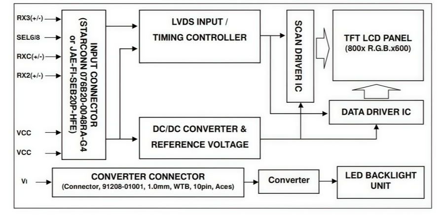
G121S1-L02 TFT LCD Module Block Diagram
The block diagram illustrates the G121S1-L02 module’s driving architecture. The LVDS Input/Timing Controller processes incoming signals and coordinates the Scan Driver IC and Data Driver IC to drive the 800 × 600 TFT-LCD panel. The DC/DC Converter and Reference Voltage circuits supply power to the driver ICs, while a separate power input supplies the built-in LED Backlight Unit through the backlight converter.
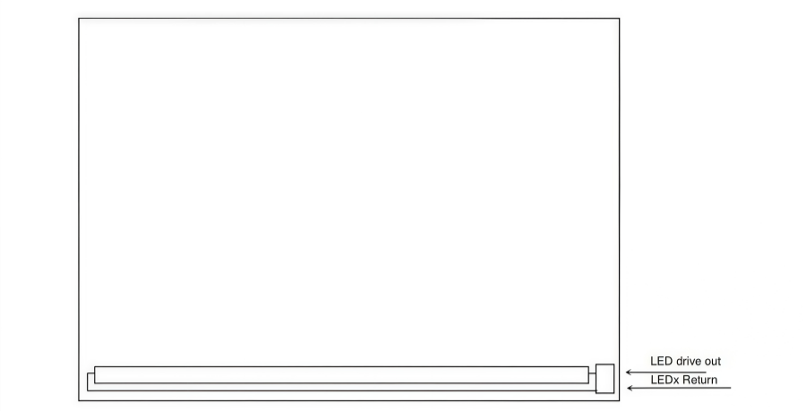
G121S1-L02 Backlight Unit Block Diagram
The block diagram illustrates the structure and driving circuit of the G121S1-L02 Backlight Unit. The LED light bar is located at the bottom of the display panel. The LED drive output supplies current to illuminate the LEDs, while the LEDx Return terminals complete the current paths, providing backlight illumination across the screen.
LVDS Signal Interface & 20-Pin Connector Pinout
The G121S1-L02 uses a 20-pin connector (such as the JAE FI-SE20P-HFE or an equivalent model). It includes single-channel, 6/8-bit selectable LVDS differential data pairs (RxO0- to RxO3+) and a differential clock signal (RxOCLK) for noise-resistant image data transmission. The interface also integrates 3.3V logic power supply pins (\(V_{DD}\)) and multiple ground pins (GND). In industrial environments with high electromagnetic interference, a shielded twisted-pair cable is recommended to help ensure stable and reliable signal transmission.
Pin Configuration
Pin Number | Symbol | Pin Number | Symbol |
1 | RX3+ | 2 | RX3- |
3 | GND | 4 | SEL68 |
5 | GND | 6 | RXC+ |
7 | RXC- | 8 | GND |
9 | RX2+ | 10 | RX2- |
11 | GND | 12 | RX1+ |
13 | RX1- | 14 | GND |
15 | RX0+ | 16 | RX0- |
17 | reLR | 18 | reUD |
19 | VCC | 20 | VCC |
Primary Industrial Applications of G121S1-L02
With its reliable industrial-grade performance, the G121S1-L02 is suitable for a wide range of industrial equipment.
1. Industrial Control Systems
The G121S1-L02 can be used as a display interface in industrial control equipment to present operating status, production parameters, operating instructions, and real-time data.
l Industrial control panels
l Industrial HMI systems
2. Industrial Automation Equipment
In automated production environments, the G121S1-L02 can serve as an operation and monitoring screen, displaying operating modes, production progress, equipment parameters, and fault alerts.
l CNC machine tools
l Automated production line control equipment
l Robot control systems
3. Test and Measurement Instruments
The G121S1-L02 can be integrated into industrial testing and measurement equipment to display measurement results, waveforms, operating data, and equipment status.
l Industrial oscilloscopes
l Electronic test instruments
l Data acquisition equipment
4. Power and Energy Equipment
In power and energy management systems, the G121S1-L02 can display voltage, current, power, operating status, and alarm information, helping operators monitor equipment performance.
l Power monitoring equipment
l UPS (Uninterruptible Power Supply) systems
G121S1-L02 Automotive Display Use Cases
In addition, the G121S1-L02 offers stable display performance and data transmission, making it suitable for certain automotive electronic display applications.
1. Vehicle Dashboard Displays
The G121S1-L02 can be used in vehicle dashboard systems to display driving information, vehicle status, warning messages, and operating data, helping drivers monitor key vehicle conditions.
l Digital instrument panels
l Vehicle status monitoring displays
l Auxiliary dashboard screens
2. In-Vehicle Infotainment Systems
The module can serve as a display component in certain in-vehicle infotainment systems, presenting navigation information, multimedia content, and system settings for convenient driver and passenger interaction.
l In-car multimedia displays
l Navigation system screens
l Rear-seat entertainment displays
3. Vehicle Monitoring and Control Systems
The G121S1-L02 can be integrated into vehicle monitoring and control equipment to display real-time system information, operating parameters, and diagnostic alerts, supporting vehicle operation and maintenance.
l Vehicle diagnostic displays
l Fleet monitoring terminals
l Automotive control system displays
G121S1-L02 Datasheet
You can refer to the official datasheet of AUO B116XTB01.0 LCD to see more details:
Handling Precautions
1) Avoid bending, twisting, pressing, or impacting the module during installation.
2) Install the module in a clean environment, free from dust and oil.
3) Follow the correct power-on and power-off sequence to prevent IC damage.
4) Do not connect or disconnect the interface connector while the module is operating.
5) Do not disassemble the module.
6) Clean the polarizer with a soft, dry cloth. Avoid chemicals and abrasive materials.
7) Keep moisture away from the module during operation.
8) Store the module within the specified temperature and humidity conditions.
9) Temperatures below 10°C may slow response time and reduce display quality.
10) Avoid displaying static images for extended periods to prevent image sticking.
ANDE Electronics: Reliable LCD Display Solutions
As a professional display supplier, Ande Electronics is committed to providing LCD modules that meet modern application needs.
We offer not only high-quality display products but also reliable technical support and flexible purchasing options. Our experienced engineering team works closely with customers to provide guidance on module selection, integration, and optimization.
Choosing Ande Electronics, then engineers and manufacturers will gain a partner focused on quality, innovation, and efficiency.